Mercedes SLK World banner
Status
Not open for further replies.

Installing the R172 version of the SmartTop Module

138K views 356 replies 81 participants last post by  Avel Du  
#1 · (Edited by Moderator)
2012 SLK 350 smartTOP Installation Addendum

This is an addendum to the installation guide for the smartTOP STHFMZ2 Control Module which can be found at: mods4cars product manual

IMPORTANT!!
here's link to the post about removing the rear speakers first: Installing the R172 version of the SmartTop Module

No need to disconnect the speakers!See post #189 for more info
mod edit: direct link to post 189


GENERAL COMMENTS:
The smartTOP guide is quite good but there are some gray areas that I hope to clarify with this narrative.
The steps listed below refer to the steps in the original installation guide and any steps that are skipped are where the original guide works just fine as is.

The first thing to do is hook the module up to a computer and check for updates, when I did my installation there was an update for the module from a just couple of days earlier to version 1.11.

For any photos in the guide that showed any wiring, I printed out as full page photographs, these turned out to be quite handy.
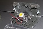
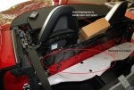
Note that the actual space where the roof control module lives is pretty small and there is not much room to work in.

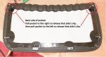
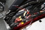
The roof control wiring connector that you have to swap wires on is quite small, which the photos in the guide don’t indicate. Make sure you have plenty of light where you do the installation so you can clearly see the connectors, slot/pin numbers, and wire colors.

The Torx screws holding the metal plate to the bulkhead are fairly large and a 3/8” ratchet socket wrench is recommended. I used a 1/4” ratchet wrench which worked but the larger size wrench would have been better.
 

Attachments

Save
#2 ·
MY ADDITIONS TO THE GUIDE:

Guide Steps 1 – 2:

When removing the various Air Guide parts keep the right and left sides separate as most of the pieces are not interchangeable. Some of the parts are stamped with an ‘R’ or ‘L’ if you do mix them up. There is a rubber O ring on each of the mounting bases that are easy to lose.
 

Attachments

Save
#3 ·
Guide Step 5:

When removing the center pocket on the rear bulk-head, first pull the top elastic part to the right to free that side’s clip from the slot underneath it and then pull the pocket towards the front of the car. That will release the clip from the slot completely. Then do the same for the left side.

Then push the whole pocket up from the bottom to free the four bottom clips from their slots, then pull the pocket towards the front of the car to release the clips completely from the remaining slots. Don’t force any of this - the clips on the back-side of the pocket are plastic and easily broken.
 

Attachments

Save
#4 · (Edited by Moderator)
Guide Steps 5 – 7:

IMPORTANT!!
here's link to the post about removing the rear speakers first: http://www.slkworld.com/slk-r172-ge...eral-discussion/22701-installing-r172-version-smarttop-module-4.html#post288005

No need to disconnect the speakers!See post #189 for more info

The next step is removing the cover that surrounds the roll-bars. If you have the Logic 7 sound system (and maybe stock) there is a speaker under the right side of the cover and another speaker under the left side of the cover. The wires running from the wiring harness to the speakers are quite short with little slack. Therefore, do not raise the roll-bar cover more than 2 – 3 inches. You have to remove the wire connectors from each of the side speakers before you can move the cover out of the way.

There is very little room to get your hand in a good position to release the connector from the speaker (I have big hands so it may be easier for other folks). For me, the speaker connectors would not budge and I broke one of them in the process. Only pull the connectors straight out from the speaker socket. If you try to wiggle them out by moving them left or right you’ll break it as I did. Take your time here as replacing the speaker connectors is a real pain in the ***.

What’s weird is the center speaker has the same connector and it released right away but it also is out in the open where you can get a good grip on it. Also the center speaker wires have plenty of slack - go figure!

If you do break a connector, the part number for the socket (plastic cap small) is 0305452828 and the part number for the crimp contact (female) is 0085455526. Both the crimp and the socket are quite small and delicate and difficult to install without the proper tools.
 

Attachments

Save
#191 ·
Smart Top install successful but...

Guide Steps 5 – 7:

IMPORTANT!!
here's link to the post about removing the rear speakers first: http://www.slkworld.com/slk-r172-ge...eral-discussion/22701-installing-r172-version-smarttop-module-4.html#post288005

The next step is removing the cover that surrounds the roll-bars. If you have the Logic 7 sound system (and maybe stock) there is a speaker under the right side of the cover and another speaker under the left side of the cover. The wires running from the wiring harness to the speakers are quite short with little slack. Therefore, do not raise the roll-bar cover more than 2 – 3 inches. You have to remove the wire connectors from each of the side speakers before you can move the cover out of the way.

There is very little room to get your hand in a good position to release the connector from the speaker (I have big hands so it may be easier for other folks). For me, the speaker connectors would not budge and I broke one of them in the process. Only pull the connectors straight out from the speaker socket. If you try to wiggle them out by moving them left or right you’ll break it as I did. Take your time here as replacing the speaker connectors is a real pain in the ***.

What’s weird is the center speaker has the same connector and it released right away but it also is out in the open where you can get a good grip on it. Also the center speaker wires have plenty of slack - go figure!

If you do break a connector, the part number for the socket (plastic cap small) is 0305452828 and the part number for the crimp contact (female) is 0085455526. Both the crimp and the socket are quite small and delicate and difficult to install without the proper tools.
I broke the connections to the center and rear passenger speakers trying to remove them, and now I'm wondering if I get the replacement small plastic socket, first how do I remove the existing connector piece thats stuck in the socket and two, do i solder it back together? HELP!!!
 
#5 ·
Guide Steps 5 – 7 Continued:

Looking at the photo below of the underside of the roll bar cover on the driver’s side below, I now realize that you may be able to remove each of the side speaker housings from the roll bar cover before the roll bar cover is lifted at all.
That would make disconnecting the speaker connectors much easier and must be how they do it at the factory in the first place. Something for someone else to try!
 

Attachments

Save
#6 ·
Here are the socket and crimp connectors and their part numbers:
 

Attachments

Save
#7 ·
Guide Step 9:

The guide says to loosen all of the ten Torx screws on the bottom of the metal plate, I actually removed the five on the passenger side to give me more room to work with.

Guide Steps 10 – 11:

I wedged the shipping box that the module came in into the space between the bulk-head and the metal plate to maximize the work space.
 

Attachments

Save
#8 ·
Guide Step 12:

Pay attention to the slot numbers on the connector before tapping the wires to be sure that you have the correct ones.
 

Attachments

Save
#9 ·
Guide Steps 13 – 15:

When the Guide refers to “pushing in the locking tab”, that tab is underneath the white ‘lever’ not to the side as the photo implies. Pushing up the bottom of the white lever while also pushing the lever to the right will free it.
 

Attachments

Save
#10 ·
Guide Steps 16 – 19:

For all of these steps double check that you are working with the correct slot numbers on the connector and the correct wire colors before releasing the wire contacts from the connector.
Then double check that you have the correct wire color for the correct slot number before you push the wire contacts from the smartTOP wiring harness into the connector.
Finally make sure the wire colors match what the Guide says before making the connections in step 19.
 

Attachments

Save
#11 ·
Guide Step 20:

After all the connections have been made and you have pressed the unlock button on the key fob once, make sure that the Green LED is blinking as stated in the Guide. This is the only chance you have to be sure the module is actually functional before you put everything back together.
You cannot do any other testing of the roof operation until everything is reassembled.
 

Attachments

Save
#12 ·
When putting everything back together, the two carpet brackets are not interchangeable, but they are marked on the back which goes on the right side and which goes on the left side.
 

Attachments

Save
#13 ·
One final note, when I had my module hooked up to my computer, I programmed all the settings I wanted. However, once the module was installed in the car, all the settings reverted back to the defaults. No big deal but something to be aware of.

I found the control matrix chart at the end of the smartTOP Operation and Programming Guide very useful when programming the module in the car and keep a copy of the matrix in the car.
 
Save
#14 ·
Thank you for the write-up and tips.
 
Save
#16 ·
Thank you this is awesome! I'm gonna have my mechanic install the smarttop for me sometime this week when it comes in. I've already received the "add a circuit" from slkstore, but the smarttop was shipped direct from the manufacturer and I havnt recieved it yet. Thanks for this writeup its awesome!
 
#21 ·
Thank you this is awesome! I'm gonna have my mechanic install the smarttop for me sometime this week when it comes in. I've already received the "add a circuit" from slkstore, but the smarttop was shipped direct from the manufacturer and I havnt recieved it yet. Thanks for this writeup its awesome!
I don't know that the add-a-circuit will work for the R172 since the module is so far away from the fuse box.
That is one area where the R172 installation is less problematic than the R171 installation. The wires you tap for the power connection are very specific as to slot numbers. Whereas for the R171 you had to guess what wires to tap from a bundle of them.
Major kudos to Mods4cars to getting the R172 version out even before most of us could even order the car!!
 
  • Like
Reactions: rankinthomas46
Save
#18 ·
Omg Rabbit did you put any miles on the new car before you took it apart? And since it is a brand new R172 and lets just say something goes wrong how will it affect you warranty since you opened up the new Slk before the Mb Mechanic had a chance to learn on your new R 172?
 
Save
#20 ·
I had the car for two weeks and about 250 miles before I took it apart. Since I had prior experience with smartTOP for the SLK I was fairly confident that it would work out OK.
 
  • Like
Reactions: Ralph Coulson
Save
#22 ·
Thank you, maybe I should change my sig to - 1 R172 -?
 
Save
#24 ·
Oink, oink.
 
Save
#29 ·
If he followed the suggestion to thread the USB connection up to the central pouch on the vertical wall of rear cockpit bulkhead, then the software can be updated easily via a laptop with internet connection.
 
Save
#32 ·
They have an email newsletter that mentioned the rebate, so I sent them the link.
The rebate actually expired June 30th but they gave it to me anyway, a class act all the way.
 
Save
#36 ·
Even so, it is well worth the effort and cost.
 
Save
Status
Not open for further replies.
You have insufficient privileges to reply here.