Mercedes SLK World banner
Status
Not open for further replies.

SmartTop Roof module Install for the R171

72K views 13 replies 4 participants last post by  jbanks15  
#1 · (Edited by Moderator)
Use this attached pdf. if photos are 'broken' from photobucket

There were a couple of requests to try and have the SmartTop install in one place instead of many posts scattered all over. So here's an attempt to do so.


ADMIN: Special thanks to Moe, Eddy, and Brian for this PDF attachment with the latest tips and tricks to a successful Mods4Cars Smarttop roof module install!

JB edit: What is the SmartTop:
What is this SmartTOP all the members keep talking about?
 

Attachments

Save
#2 · (Edited by Moderator)
Use this attached pdf. pb photos are ****

Preliminary Notice

This is meant to supplement/clarify the installation instructions from the manufacturer of the SmartTop module for the R171 and is by no means a comprehensive guide. Always refer to the instructions by the manufacturer or email them when in doubt. The example will be that for left-hand-drive vehicles and will include steps for drawing power from the fuse box located at the left side of the dashboard (as an alternative to crimping the correct red wire, this may not be possible for right-hand-drive vehicles).

Many of the photos are from Shinigami (from another forum) and will be acknowledged as such.

The narrative and photos may be submitted in several sequential posts as I gather my thoughts. This may take several days/weeks. The narrative and photos may be edited or replaced later if there's better material available.

JB edit: issue to be aware about,,,,,very rare instance:
The other end of the wires that plugs into the Smart Top module might have been wired wrong. Yes, sure enough the polarity was switched around in the end that plugs into the module. My module if you are looking at it with the plug in it and the words are right side up had red, red, black from left to right. It should have had all the reds on the top row and the brown, black, black on the bottom row. We took apart the small connector that was wrong and switched the wires around and everything worked perfectly.
 
Save
#3 · (Edited)
Tools and materials needed

Please read through the whole set of steps and instructions in addition to using the photos as a rough reference.

1, Small sized flat head screwdriver (to open the cover that hides the torx screw holding the vertical kick panel)

2, Medium sized flat head screwdriver (to open the fuse box cover at left side of the dashboard)

3, T-20 Torx screwdriver (to remove 2 screws that hold the underdash panel, remove the screw that holds the vertical kick panel)

4, 10 mm socket wrench (to release the bolt that holds the factory ground wire)

5, Insulated bullet/butt male and female connectors (for gauge 18-22 wire, and Gauge 16 wire)

6, Crimping tool

7, Add-a-circuit (if it didn't come with the SmartTop) or OEM fuseholder & contact spring

8, Cardboard box or rubber/plastic-capped wooden dowel/rod (~10.5 inches long) to prop carpet

9, Red primary wire AWG 16 or 18 (~3 ft long, this will be cut to desired length). Later SmartTop models have 3-ft long wires that will reach the factory ground near the engine hood/bonnet release lever, so only 1-foot length may be needed.

10, Good light source

Optional

11, Masking tape

12, Iced tea or cold beer, whichever brew one prefers :D
 
  • Like
Reactions: GomerPyle
Save
#4 · (Edited by Moderator)
Step 1, removing the door sill

Do the following before removing the door sill (per manufacturer's instructions):

1. Turn off the ignition and remove the key
2. Wait at least 5 minutes before lifting and removing the cover to the CANBUS terminal block

Retract the roof if indoors/protected structure.

Move the seat all the way back.

Remove the door sill by lifting it from the back and work towards the front. Do this by grabbing the sill with both hands at the inside surface (carpet area) and lifting with moderate force upwards. You will hear some creaking sounds as the plastic door sill is released from friction clips underneath. The sill is removed by lifting and sliding it outwards to clear a long metal lip that also serves to hold the plastic door sill. Take note on how the small U-shaped channel at the outer part of the door sill slides into the metal lip of the car body (at area of green arrow labeled PULL in photo below). You will need to remember this when reattaching the door sill after the install. See photo below:

Image

Photo by Shinigami


Next photo shows the metal friction clips (red arrow), total of 4, and the metal lip (green double sided arrow).

Tip: Cover the friction clips with wide enough masking tape to prevent scraping or cutting your hands and forearms. They have sharp edges.

Image

Photo by Shinigami
 
Save
#5 · (Edited by Moderator)
Step 2, removing the kick panel

Remove the 2 torx screws (outer and middle) and loosen the 3rd (inner) from the horizontal under dash panel as shown below. This will make the removal of the kick panel easier. Pull down partially the under dash panel by perhaps 6 inches at its junction with the kick panel.

Image


Use a small flat head screwdriver to remove the oval cover that hides a torx screw at the kick panel. Remember to keep all removed screws and covers in a secure area/container for easy retrieval later. See photo below:

Image


Remove the torx screw that anchors the kick panel to the metal body. Take note of the semicircular lip that is part of the hood/bonnet release lever as illustrated (green elliptical in the photo above and below). Make sure this lip is showing when the kick panel is reassembled after the install or you'll have a rattling sound from a loose kick panel. Also note the rubber seal or moulding around the door (red arrow in photo above). This seal should cover (i.e., not underneath) the kick panel when it is reassembled. It can be lifted or adjusted to cover the kick panel when reassembling later with a medium-sized flat head screwdriver.

Image

Photo by Shinigami


Photo below shows the orientation of the underdash panel (red outline) to the kick panel. The larger green ellipse shows where there is a small lip at the kickpanel that must clear the underdash panel, and the smaller green ellipse shows where there is a protruding tab from the underdash panel that projects towards the front of the vehicle to engage a small slit in the carpet. The slit found on the carpet should be reinserted into this tab when reassembling later.

Image

Photo by Shinigami


The kick panel is removed by pulling downward and then towards the back of the vehicle. This may take some wiggling and maneuvering to free the panel. Take your time in doing this to avoid breaking any plastic tabs or lips.
 
Save
#6 · (Edited by Moderator)
Step 3, Accessing the wire harness/loom and exposing the CANBUS terminal blocks

Lift the carpet upwards and inwards toward the center of the vehicle. Keep the carpet propped away from the door sill and kick panel area with a small box or wooden dowel (about 10.5 inches long). I use a brass rod of the same length from a discarded bathroom sink drain assembly. Remember to cap the ends with rubber grommets to prevent damaging the paintwork and the carpet. Also be very careful where you place the dowel/rod as the Teleaid speaker is nearby.

Photo below shows the carpet being lifted and the green circles show where the 4 tabs are on the wire harness/loom channel cover.

Image

Photo by Shinigami


The 4 tabs that hold the cover are inverted L-shaped tabs with the short leg of the L facing the center of the car. Push the tabs outward (away from the center line) with fingers from one hand as you lift the black plastic cover with the other hand. This may require some force and part of the plastic cover that engages the tabs may stretch or break in the process. Do not panic as the harness cover will snap back in place and close securely even if one or two breaks.

Tape the wire harness cover open with masking tape or use a small box as illustrated below. The CANBUS terminal blocks will now be visible and can be accessed.

Image

Photo by Shinigami


There are 2 CANBUS terminal blocks. You want the access the front one (towards the front of the vehicle). Take note to see where there may be empty spaces (no plugs with wires) in the CANBUS terminal block.

Simply lift the front CANBUS terminal block from its seat inside the wire harness channel. It is held in place by slits in the channel that the CANBUS cover slides into. See photo below.

Image

Photo by Shinigami
 
Save
#7 · (Edited by Moderator)
Step 4, Removing the CANBUS terminal block cover (CANBUS cover for short)

Warning: Do not attempt to pull any of the wired plugs until the CANBUS cover has been released and removed. The plug will not come off. You run the risk of pulling and breaking the wires instead.

Moreover, when attempting to remove a wired plug (after the removal of the CANBUS cover) only pull straight out from the body of the plug itself and not from the wires or you run the risk of breaking the wires.
(big headache if you break the wires)


Before removing the CANBUS cover, have a small strip of masking tape handy. Re-read the manufacturer's instructions to determine which male plug to pull. Prior SmartTop instructions states to use the 3rd plug, counting from the side where there are empty slots. The empty slots are included in the count. In the last illustration on Step 3 (see above), that would be the plug at the left of the picture. The first two counting from the left are empty. Later SmartTop instructions state to use the plug next to the one that has a brown and brown/black wire pair. At any rate if your first attempt at finding the correct plug fails, stay calm, the later SmartTop models have a flashing green LED, called InstallAID LED, to guide you. (Please review the manufacturer's instructions)


Tip: Once you've determined which plug to pull later, use the strip of masking tape to mark the wire pair of the plug-of-interest.


To remove the CANBUS cover:

Take a closer look at the CANBUS cover, the side that has a row of small square windows. There are 2 small indents (red arrows) on the cover as illustrated below:
Image


The following tip/procedure is from a German website.


1. Insert a flat wooden stick to each side (narrow) of the CANBUS cover. German site used wooden matchsticks. I used the wooden coffee stirrers from a coffee shop. Measure and cut/trim the wooden inserts to the same length as the whole CANBUS assembly (see photo 1 below). Do the cutting away from the assembly to avoid cutting any wires and reinsert the flat wooden sticks. Secure the sticks to lower end of the CANBUS assembly w/masking tape (see photo 2 below). The 2 wooden sticks when secured in place will release the locking tabs found at the inner surface of the CANBUS cover.

2. Insert a small flat head screwdriver unto one of the 2 tiny indents (mislabeled tabs in photo 2) on the CANBUS cover. See photo 2 and Photo 2a. They are molded on the side where there are many small square windows. (I used 2.5mm jeweler's screwdriver). Slowly use a prying motion with the screwdriver as you work away from the center of the CANBUS cover towards where one of the wooden inserts are. Notice the direction of the force to remove CANBUS cover as seen in photos 2 and 2a. You can make removal easier if you use the index finger of one hand pushing/pulling in the same direction while using the screwdriver with the other hand. Work to release one side only. When one side releases it is easy to remove the CANBUS cover as seen again in photo 2 as the whole cover now pivots free.

3. Trim the tab located at each end (of the CANBUS cover) with a sharp hobby knife (exercise extreme care when working with sharp instruments) and sand smooth with motor tool. See photos 3 and 4. This will make removal of the cover easier in the future without the need for the wooden sticks. Slight finger pressure and small screwdriver and the cover comes off in a jiffy.


Photo 1, wooden stick(trimmed) at side of CANBUS cover

Image


Photo 2, note masking tape used to secure wooden stick and direction of force to effect removal of the cover

Image


Photo 2a, showing small flat head screwdriver in place and wiggling towards one side and the direction of prying motion and removal.

Image


Photo 3, trim the tabs for future use

Image


Photo 4, trimmed area on CANBUS cover

Image
 
Save
#8 · (Edited by Moderator)
Step 5, assemble the pins/connectors, and connect to CANBUS terminal block

A. Assembling the pins

Assemble the pins (thin long ones and the squarish ones) to their respective CANBUS connectors, as supplied with the SmartTop module.

The thin long ones go into the female/larger connector; and the squarish ones go into the male/smaller connector.


The next photo illustrate that the short squarish pins go to the short connector plug, and the long thin ones go into the longer connector plug (photo does not show the exact placement). Exact placement of red wire to the no.1 position will be shown in subsequent pictures.
Image


There are numbers (1 and 2) molded unto the side where the 2 square holes are located. The red wire goes into the square opening with no.1, the black wire to no. 2 (for the SLK).


Photo below shows where the molded numbers (highlighted by silver paint)are located on the smaller/male connector.
Image


Positions of the molded numbers (highlighted by silver paint) on the larger/female CANBUS connector is illustrated below:
Image


Note the orientation of the pins, the side where there is a spring extension (locking spring mechanism) is aligned to the same side as the locking tab on the CANBUS connectors. Gently insert and slide the pins in and you should hear/feel a gentle click. Once both pins are in, press the locking tab on the CANBUS connector so it snaps in place. The pins are now securely in place inside the connectors.


Orientation of the squarish pins to the smaller/male CANBUS connector prior to insertion:
Image


Orientation of the thin long pins to the larger/female CANBUS connector before insertion:
Image


B. Connect the two assembled CANBUS connectors to the CANBUS terminal block

Insert the male plug from the SmartTop module to the slot that you just pulled the plug out from (blue/green wire pair in illustration below, will be red and black from current SmartTop). Insert the male plug that you removed and tagged earlier with the masking tape to the female receptacle (larger cap or connector) of the SmartTop module (next to the thumb in the picture).

This completes a path that leads to the SmartTop, and from the SmartTop to the CANBUS terminal block.

Image

Photo by Shinigami


Lay this assembly loosely inside the wire harness channel.
 
Save
#9 · (Edited by Moderator)
Step 6, Connecting the ground and drawing power from the fuse box

A. Cutting and crimping in new connections to SmartTop module


Cut the end connectors to the + (red wire) and ground wire (brown wire) from the SmartTop module.

Image


Connect and crimp a large U-shaped connector to the ground wire (after stripping the insulation) of the SmartTop module. Connect and crimp a male butt/bullet connector to the red + power wire of the SmartTop module. See photo below.

Image


B. Connecting to the factory ground

Connect the ground wire from SmartTop to the factory ground located near the engine hood/bonnet release lever. Loosen the 10 mm bolt and insert the U-shaped connector. Retighten the bolt.

Image


JB Edit added add-a fuse info

http://www.slkworld.com/general-dis...iscussion/482641-correctly-adding-accessory-using-add-fuse-slk.html#post3982273


C. Drawing power from the fusebox

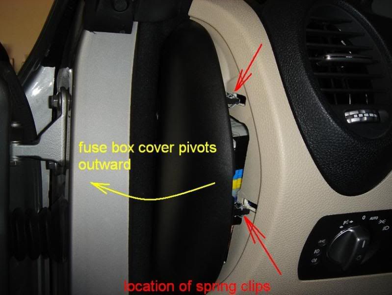
Locate the cover to the fuse box at the left side of the dashboard, the car door must be open. At the bend of the cover is a slot to which one can insert a medium- to large-sized flat head screwdriver. Yellow arrow shows where the slot is located in photo below.

Image


Next photo shows insertion of the flat head screwdriver.

Image


Pry this panel open, it is held by 2 spring clips which will be evident as the cover pivots open.

Image


Remove the fuse box cover by gentle pulling, after it pivots free from the spring clip anchors.


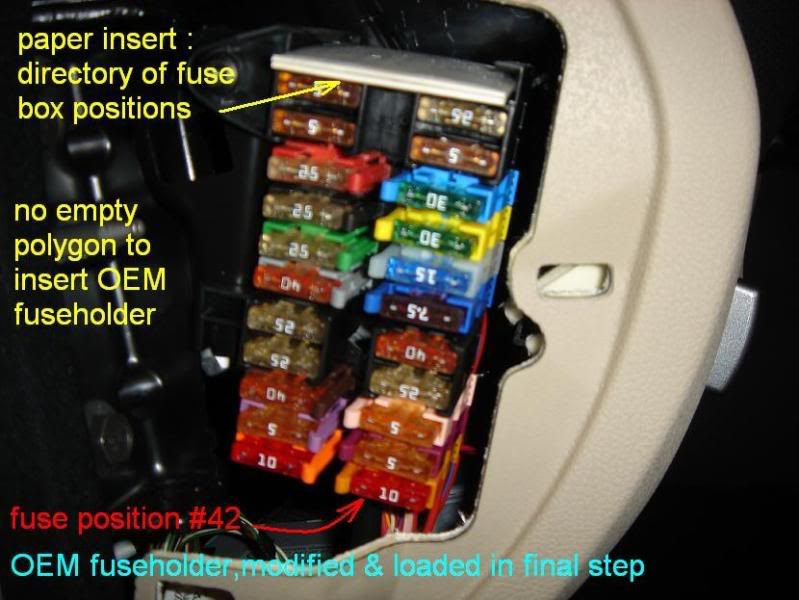
Photo below is of the open fuse box, red arrows point to open spots where OEM fuse holder may be inserted (if not using the Add-a-circuit to tap power from an existing circuit, hence its name):

Image


The next few procedures are mainly to effect connection from the SmartTop module to the power source at the dashboard fuse box.


Cut the tube connector that came with the Add-a-circuit and discard the tube connector. Strip about 10mm of the insulation off the wire and crimp a female bullet connector in its place (for the appropriate gauge wire, IIRC AWG 14 or AWG 16).
Image


Photo below shows insulated female connector in its place.

Image


Using a 2- or 3-ft long AWG 16 or 18 red primary wire (stranded), crimp an insulated male bullet connector to one of its stripped end. Connect this to the female connector of the Add-a-circuit. On the other end of the red primary wire, crimp an insulated female butt/bullet connector. You are in effect creating an extension wire from the Add-a-circuit.

The later model SmartTop modules come with a 3-ft long red + power wire, so you may need only a 12-14-inch long (maybe even less) red primary wire instead of the 2 or 3-ft-long red primary wire.

Remove the fuses that came attached with the Add-a-circuit.


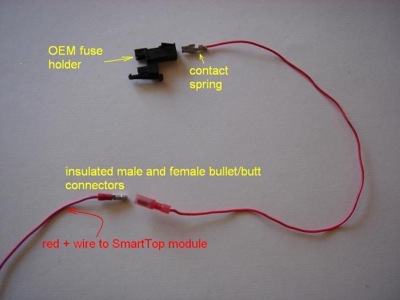
Below is a photo of the schema using OEM fuse holder, part no. A003 545 13 01, (instead of Add-a-circuit), contact spring, part no. A004 545 00 26, red primary wire (AWG16 stranded), female and then male insulated bullet connectors, and +12V feed red wire to SmartTop module. You may elect to cover the female-male connection with a rubber sleeve for added safety/security. Notice the fuse holder is empty, i.e., no fuse inserted.

Image


Below is a schema on drawing power from the fuse box with either the Add-a-circuit or OEM fuseholder. Notice again, no fuse(s) is inserted

Image


Warning: We do not want the red wire to be live at all until the final stages of the install or risk shorting a circuit or two and blowing fuses (another potential big headache).

Determine which circuit you want to tap from the fuse box. I used the passenger powered seat in one install (check the fuse box directory on the paper that's inserted at the fuse box to determine which one to use). Remove that particular fuse with the fuse removal tool (came with your vehicle or readily available from auto parts store) and note the particular fuse location (now empty) that you want to tap the power from. Remember to leave the 2 fuse slots on the Add-a-circuit EMPTY at this time. DO NOT insert the empty Add-a-circuit at this time.


If you're using the OEM fuse holder (instead of the Add-a-circuit, and already assembled with contact spring and primary wire in place as illustrated in the schema above), then pick an unused or open spot in the fuse box area and insert the empty OEM fuse holder. Take note that the OEM fuse holder has a small L shaped rib that fits unto a slot of an existing fuse holder above. If all the spots on the fuse box are taken because of the many optional equipment installed in your car, then one can use #42 position (see photo below). Position #42 is usually empty in LHD (left-hand drive) vehicles. Some OEM fuse holder may have a different polygonal shape at the side where it inserts into the fuse box. This may have to be modified by a motor tool to effect proper insertion and alignment, especially to position #42 .

Image


Thread the red wire down the kick panel area. Remember that there is no power to the red primary wire from the fuse box as the fuse/fuses have not been inserted. Connect the male butt/bullet connector from SmartTop module to the female butt/bullet connector. (NOTE:I usually insert a flexible rubber tubing to the male side of the connection before joining the male and female together. I slip the rubber tubing to further insulate the connection) See the next 2 photos below:

Image


Image


This completes a path from the fuse box (where the add-a-circuit( or OEM fuse holder) is still empty at this time) to the SmartTop module.


Clear work area of any tools or non-essential bits.


Insert 2 ATO fuses to the Add-a-circuit. Use the same amp rating (as was removed from the original place in the fuse box) to the side nearest the fuse box and a 5 amp rating to the side nearest the red primary wire of the Add-a-circuit. Insert the now loaded Add-a-circuit into the fuse location that you want to draw power from.


Photo below shows loaded Add-a-circuit before insertion to the fuse location of interest.

Image


If using the OEM fuse holder, insert a 5 amp fuse.


Check the SmartTop to see if the green InstallAID LED of the SmartTop module (if not try turning ignition to position 1 or 2 without starting the engine) flashes or blinks almost once every second. If it does then the connection is correct.

Check the manufacturer's troubleshooting guide regarding the InstallAID LED if needed. Sometimes the wiring for your vehicle is different because of the different optional equipment. Since the CANBUS cover is still not reassembled, one can determine the correct plug through trial-and-error (disconnecting and connecting plugs down the line) until the InstallAID LED blinks.

Once satisfied with the connection, double check and clear work area, including the cabin rear shelf and others so that the roof will be free to operate. Do not reassemble anything yet. Remove key from ignition if this was inserted earlier, close the door. Try 3 clicks on the key fob and see the magic happen :)


Relax, have a nice glass of iced tea and enjoy the moment.

Reattach the CANBUS cover.


D. Locate/place the SmartTop module within the wire harness/loom channel

The SmartTop module can be placed in between the 2 CANBUS terminal blocks. The side extensions of the SmartTop module will fit under the CANBUS terminal blocks. Reseat the front CANBUS terminal block. SmartTop module is now nicely "sandwiched".

Image


Use a couple of velcro straps to neatly anchor the ground and power wire alongside the wire harness/loom. Close the cover and you're ready to place everything back in order.

Image


Just remember the following, coming from the SmartTop are only 4 connections:

a. Male plug that connects to the CANBUS terminal block

b. Female plug or receptacle to which the male plug (that was pulled from the CANBUS terminal) connects

c. Ground wire that connects to the factory ground near the hood release lever

d. Red power wire that connects to the Add-a-circuit or OEM fuse holder (inserted to the fuse box at the side of the dashboard). This is done as a last step.


"Happy Modding."
 
Save
#10 ·
Awesome thread, and as usual Eddy's spot on with everything. I'll post up the differences for the RHD install this weekend after I complete mine.

Also, in the interest of keeping this "clean", I'm going to lock the thread - if you have questions or comments, please post in a separate thread, and we'll incorporate them into this one. I've also deleted a couple of comments out - again, just to keep this one clean and straightforward! (Sorry Brian!) :)
 
#11 ·
Gents - just installed the smart top in my RHD '55. The new pdf from mods4cars is spot on with the process, so I'm not going to re-hash that.

Some notes :

1] There is no easy way to get power on the right side of the car without taping a wire. I tapped the power going to the headlight control as recommended by mods4cars. I removed the headlight switch assembly to make it easier to crimp the wire. In the mods4cars instructions, remove the torx screw on the blue connector to remove the switch.

2] Ground is in the same place, simple opposite side of the car for Eddy's pictures. I used a standard crimp-on ring.

3] Removing the accelerator is highly recommended. It's a bit fiddly, as it's a counter-sunk 10mm nut holding it in place - I ended up using a deep 10mm socket and a my smallest ratchet to remove it, as you are between the floor and the peddle. The nut is covered with a plastic cap, it's easy to pry up, but again, a pain to get to.

4] Remove the lower dash cover is almost the same as in a LHD car, but you have an electronics module that I don't remember on my LHD. It's a typical MB plug, single notched clamp holding it in place. In my car, there are two sockets on this, but only one had a harness going to it.

5] If you choose to completely remove the panel - I did, as I found it made things easier with running the power wire - you need to unplug the lamp, the harness described above, and the ODBII connector. The OBDII connector has a slide retention mechanism, see the photos - basically you grab it as shown and "slide" it towards the front. The ODBII connector than pops out.


So all in all it's a bit more effort than on a LHD car, and I don't see an easy way to do it without tapping for power.

This is about my 5th install now, so CANBUS cover has gotten easy! ;-)

Connections on Drivers side lower cover panel :
Image


How to remove ODBII connection :
Image
 

Attachments

#12 ·
I removed the headlight switch assembly to make it easier to crimp the wire. In the mods4cars instructions, remove the torx screw on the blue connector to remove the switch.
Done 3 RHD cars now, still never been able to remove the light switch - the fascia comes off, but I feel I'd have to apply too much force to remove the switch, BUT . . . the part of the loom that goes to the switch is long enough to be able to pull it through the RHS dash end panel, and tap into it from there.

This is about my 5th install now, so CANBUS cover has gotten easy! ;-)
Never yet had a problem with the CANBUS cover :)
 
Status
Not open for further replies.
You have insufficient privileges to reply here.